CS 5610/6610 - Spring 2021 - Interactive Computer Graphics
Project 2 - Transformations
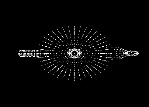
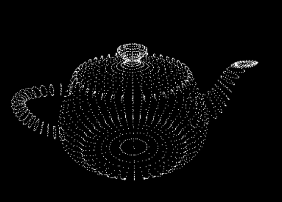
In this project we will display the vertices of an object. This will involve generating a vertex buffer, computing the camera transformations, and very simple GLSL shaders.
Requirements
The requirements of this project are separated into three steps. You might be able to verify your implementation at the end of each step, but there is no guarantee that you will have a working implementation before you complete all three steps.
- Step 1: Vertex buffers
- Open and read the vertex data from an .obj file.
You can use this teapot.obj file for your tests.
You can use the cyTriMesh code release for parsing the obj file. - Your program must take the name of the .obj file as its first command-line argument.
- Generate and bind a vertex array object.
You can use the GLEW library for initializing OpenGL extension functions. Do not forget to callglewInitafter you create the OpenGL window. - Generate a vertex buffer and set its data using the vertices you read from the .obj file.
You can refer to this tutorial regarding the steps for generating the vertex buffer. Note that this tutorial does not include a vertex array object, but your implementation should. You can find a detailed description of vertex array objects and how to use them here. - Draw the contents of the buffer in your display function.
- Open and read the vertex data from an .obj file.
- Step 2: GLSL shaders
- Write a simple vertex shader and a simple fragment shader.
- The vertex shader should transform all vertices by multiplying them with a model-view-projection matrix.
- The fragment shader should simply return a constant color value.
You can use any color value you like. - Compile the shaders into a GLSL program and use it for your draw call.
You can use the cyGL code release for handling the shaders.

- Step 3: Transformations
- Set the camera transformation using two rotation angles and one translation that determines the distance of the object from the camera.
You can use the cyMatrix code release for setting up your transformation matrices. - The left mouse button (and drag) should adjust the camera angles.
- The right mouse button (and drag) should adjust the camera distance.
- Use perspective transformation for projection.
- Send the matrix to your vertex shader as a uniform parameter.

- Set the camera transformation using two rotation angles and one translation that determines the distance of the object from the camera.
Additional Requirements for CS 6610 Students
- Pressing the F6 key should recompile your GLSL shaders.
- Center the object (using its bounding box) by adjusting the transformation matrix.
Optional
- Pressing the P key switches between perspective and orthogonal transformation.
- When using orthogonal transformation, use one over camera distance as a uniform scale factor.
Notes
You can use GLFW instead of FreeGLUT, if you are having problems with GLUT/FreeGLUT or if you would prefer GLFW.
Mac OS X users can follow this tutorial for installing GLEW.
_