CS 6620 - Fall 2017 - Ray Tracing for Graphics
Project 1 - Ray Casting
In this project we will begin writing a ray tracer. The input will be an XML file describing the scene and the output will be an image in PPM format. Source code for reading the scene file is provided.
Requirements
- Read the given XML scene file with the format explained below.
- Generate camera rays.
- Compute ray-sphere intersections for all spheres in the scene.
- If a ray doesn't hit any object, the corresponding pixel should be black.
- If a ray hits an object, the corresponding pixel should be white.
- Create a normalized z-buffer image.
XML Scene Format
Here we define a basic XML format for describing the scene. Upcoming projects will have additional descriptions and we will define them as we need them.
Here is an example scene file:

<xml>
<scene>
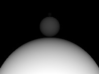
<object type="sphere" name="sphere1">
<scale value="25.0"/>
<translate x="0" y="50" z="-25"/>
</object>
<object type="sphere" name="sphere2">
<scale value="5.0"/>
<translate x="0" y="50" z="5.1"/>
<object type="sphere" name="sphere3">
<scale value="0.2"/>
<translate x="0" y="0" z="1.2"/>
</object>
</object>
</scene>
<camera>
<position x="0" y="0" z="0"/>
<target x="0" y="20" z="0"/>
<up x="0" y="0" z="1"/>
<fov value="40"/>
<width value="800"/>
<height value="600"/>
</camera>
</xml>
Notice that all the objects are declared inside the "scene" tag with an "object" tag. The only object type we will have in this project is "sphere" which denotes a unit size (radius = 1 unit) sphere centered at the origin. The object transformations can be translate, rotate, and scale (in this project translate and scale only) that are declared under the object tag. The transformations are applied in the order that they appear in the XML file. Multiple "scale" and "translate" tags can be defined for the same object. Examples of transformations are given below.
<!-- Translate -->
<translate x="3.04" y="50" z="-25"/>

<!-- Translate in y direction only -->
<translate y="7.8"/>

<!-- Rotation around an axis (30 deg) -->
<rotate value="30.0" x="1" y="1" z="0"/>

<!-- Rotation around z axis -->
<rotate value="-10" z="1"/>

<!-- Uniform Scale -->
<scale value="5.0"/>

<!-- Nonuniform Scale -->
<scale x="1.5" y="0.5" z="2.1"/>
Some elements include only a scalar value, others include vectors defined by attributes x, y, and z. Some elements, such as rotate, require both a scalar value and a vector. Elements that require a vector only, such as scale, can also be specified using a scalar value only, which would set all three components of the vector to the specified scalar value. If both a vector and a scalar value are provided, and the element expects a vector only, the scalar value is multiplied by the provided vector values. If only some components of a vector are specified, the other components are taken as zero.
Object descriptions can also be nested. In that case, all transformations of the parent object also apply to all of the child objects. Child objects can appear before or after (or in between) transformations in the XML file. Regardless of the order, all transformations of the parent object are applied to all of the child objects.
The scene file also includes a "camera" tag that describes the view angle. The size of the final image to be rendered is defined along with other camera parameters (see the example above).
You can begin your tests using the simple scene file below, which makes the camera coordinate coincide with the world coordinate.
<xml>
  <scene>
    <object type="sphere" name="sphere1">
      <scale value="5.0"/>
      <translate x="0" y="0" z="-25"/>
    </object>
  </scene>
  <camera>
    <position x="0" y="0" z="0"/>
    <target x="0" y="0" z="-1"/>
    <up x="0" y="1" z="0"/>
    <fov value="40"/>
    <width value="800"/>
    <height value="600"/>
  </camera>
</xml>
Source Code
The following source code files are provided to help you with this and upcoming projects. You are not required to use them, but it is highly recommened that you use them and refrain from modifying them.
- scene.h: Includes base classes for scene management.
- cyPoint.h: Point/vector classes from cyCodeBase, used by the scene.h file.
- cyMatrix.h: Matrix classes from cyCodeBase, used by the scene.h file.
- xmlload.cpp: Includes the LoadScene() function that parses a given scene XML file using the TinyXML library.
- objects.h: Includes the description of the Sphere class used by the xmlload.cpp file.
- viewport.cpp: OpenGL based preview and user interface launched by calling the ShowViewport() function. It requires GLUT or FreeGLUT.
- TinyXML library for parsing the XML files, used by the xmlload.cpp file.
- LodePNG library for saving PNG image files, used by the scene.h file.
Optional Feature Suggestions
- Multi threading.
Student Project Pages


_